
I’m not sure replacing the layshaft and rear cover is really a rebuild, but hey, I’ll give myself whatever unearned credit I can on this car.

You may remember this box had its rear cover shattered in an accident, and the world’s lamest bodge tried to compensate for that. That bodge resulted in the broken bolts detailed in the previous post, and the engine/gearbox ended up resting on the tail end of the layshaft. Above is the new layshaft and various related bits, including my bright pink…dummy layshaft, used on the E-Type rebuild and a reminder it’s ok to hoard garage stuff…as long as you can remember you have it! (The socket extension is going to be used to lift the shaft into mesh with the other gears.)

I took the time to sand all aluminum surfaces reasonably flat. This is the front cover. The seal is new.

Here the main shaft is in place, ready for the input shaft. Note the nose of the shaft. Guess what I discovered on the bench when I was done re-assembling the transmission for the first time?

The caged needle bearing which goes onto that shaft. Oops. That was not a happy moment.
Even less happy was discovering I could not shift the box into third and fourth gear after putting it back together again. Now, you may remember that this same issue prompted the tear-apart of the E-Type (on a box I didn’t assemble), and I’m super-careful about making sure that syncro hub is properly aligned.
What happened this time? On the second dismantling, the second gear syncro hub flew apart, ball bearings and springs everywhere. There is also a single plunger in that hub, which is a slightly different length (longer) than the two in the third/fourth gear hub. My theory: I put that longer plunger into the third/fourth gear hub accidentally. In any case, Mr. Moss had to come apart again. I think some paint peeled from the heat of the cursing.

This is the new rear cover with the new layshaft and the reverse gear shaft in place. I’ve been trying to figure out why they have you mount these two shafts into the cover before attaching it…I suspect it’s because it otherwise might be impossible to reliably get the shafts into place.

Here are the bits for the extension, ready to go on…

Including the extended input shaft.
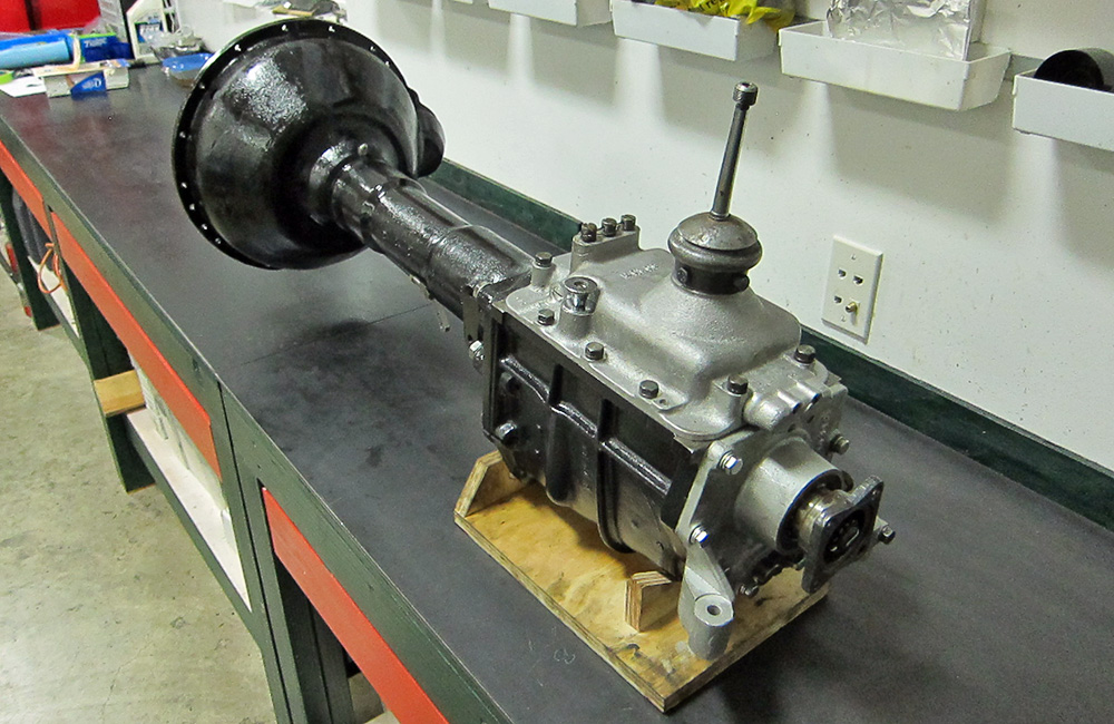
And here is the box completely assembled. It shifts into all gears! I’ve since added the proper gear knob and mounted the handbrake to the side of the extension. I’m sure a photo will turn up at some point.
words fail me… beautiful bit of work, Roger! keep up the good fight! cheers, J.