If practice makes perfect, I’ll eventually be fairly good at making Morgan rear wheel arches. I opted to make a new set after a series of cumulative errors made my previous attempts not really usable. I always tell people my only real skill when it comes to restorations is the willingness to do things over again if I think whatever I did isn’t up to scratch…even if I grumble about it. (And I do!)
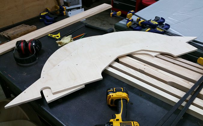
Above are new inner arch panels. Changes here are mainly the flattening of the lower arc to follow the support board, like later arches did. The original hardwood arches used a small metal plate to cover the hole left above the support board on the inside of the arch, as they would have needed a 16″ wide board otherwise.
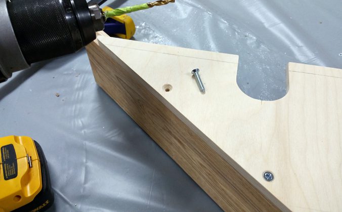
Once again, I will be using 10-24 machine screws with tapped threads in the ash to attach the arches (said screws are really clamps for the epoxy, which will be doing most of the long-term work). I’m using a 9/64″ bit to drill the ash–the plywood gets 5/32″ holes so the threads do not engage for better clamping.
I’ve counter-sunk the holes, and used my (reusable) support boards to guide the 1/4″ holes needed to add them.
The panels are half an inch long at the bottom. In the back, the (new) rear rail will be grooved to fit the board, allowing the original 1″ sill board thickness. In the front I would like to do the same thing, but when it’s time I’ll probably trim those tongues off as it’s way fussy up there.
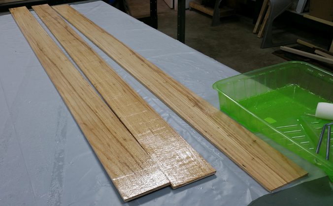
Re-sawing a 1″ thick board into three 1/4″ thick boards did not go as smoothly this time, though I’m not entirely sure why. I ended up using three 5-1/2′ lengths of ash to end up with six usable boards. I was tempted to try four 3/16″ boards instead–for a more pliable arch when putting it into the form–but it was late and my neighbor would probably have shot me if I continued using the planer…
You can see the West System epoxy, the disposable foam roller, stir stick, and plastic mixing pot and paint tray used. The table is covered with plastic sheet so the boards can be laid directly on it as we work.
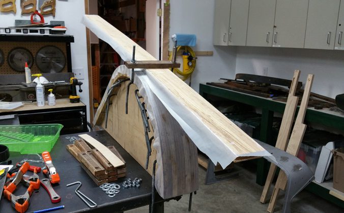
In the background, the form has been covered with fresh polyethylene sheet, and just peeking into the image to the left is the piece which will cover the top of the laminated boards to keep the clamps from becoming part of the car.
The bottom of the three boards have been coated with epoxy. At this temp, I have an hour or so of working time, every bit of which will be needed as tightening the arch to the form is tedious, time-consuming work.
I made sure that the natural arch of the boards went against the form, and roughed them up with 80-grit paper with the grain to give the epoxy a bit of a tooth to grip to. I penciled a “B” on the bottom in honor of the queen, Beyoncé–sorry, to make it clear which side of each board should be towards the “B”ottom.
I will now flip the boards one-by-one, coating the top of each, and stack on each other.
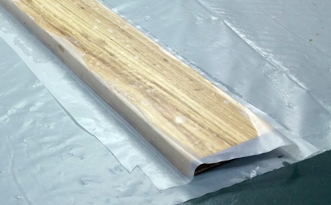
Here’s the stack with the plastic sheet on top, ready for the form. I would have made the plastic a bit narrower, as this is compensating for last time when I tried to be too clever and made the plastic barely cover the boards, which was a pain. It’s handy to be able to see the boards are flat against the form when tightening the clamps.
The first clamp in place. Sorry about the lack of photos from here until we pull the arch off the form in a couple of days–there really isn’t a lot of time to grab the phone and take photos as the clamps are added and tightened.
Clamps are added towards the front first, and the process usually involves a chain of three clamps: the one closest to the edge is tightened by hand (using a deep 9/16″ socket to make my hands slightly happier, and then the one behind it can be tightened closer to the form using a ratcheting wrench, and the one behind that can be fully tightened (eventually). As soon as the next clamp in line will go on and engage the fasteners, it’s added and the chain is moved up a link.
A ratcheting open-ended air wrench would have been a nice thing to have!
The finished arch on the form, showing the spring-back inherent in a laminated piece of wood. A four-ply arch would, in theory, have less spring-back. The form compensates for this spring-back, but the arch will still need to be compressed a bit to go into place.
It’s important to use clamps at the bottom edge of the front to pull the tail sticking out beyond the form backwards to try and keep that edge as vertical as possible. I had two clamps there, tightened as much as possible, and that edge will still have to be trimmed to be vertical. I was generously loaned/given this form, and have zero complaints about it, but it I were to make one from scratch now I would continue the form downwards with a slight curve to the back to try and compensate…
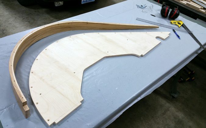
Here’s the raw arch and the inner panel it will be attached to. I made this arch half in inch wider than it needed to be, as last time I tried to be clever and made the arch out of boards almost exactly the right width, leaving no margin of error. Easy to trim, hard to put back what isn’t there!
You can see the boards will move around a bit in relation to each other, another reason to have some spare width!
In the center, everything stayed in one place a bit better, but, as you would guess, the front is similar to the back, in the opposite direction.
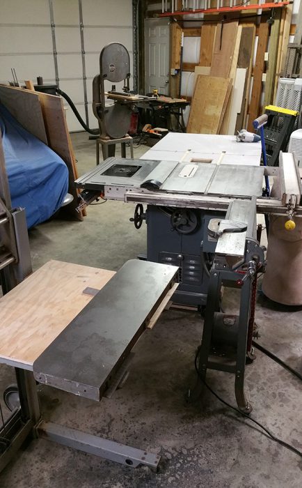
I was very tempted by an 8″ jointer on the local CL, but the owner was kind of an ass and I opted to “make do” with my 4″ jointer to true up the inner edge of the arch. I have used leveling feet to make the Unisaw in effect an extended out-feed table, and am using my Genie Lift and the table saw extension made surplus by the addition of the router table to support the back of the arch.
Having to support any board by hand when jointing or sawing is a recipe for a crappy job–a lesson I rarely seem to heed.
(The Genie Lift is a wonderfully useful tool–like a small forklift, and it will raise items from floor height to just under six feet off the ground. I just wish its lifting capacity was more than 350 lbs.
The Delta tools are a band saw from 1947, Unisaw from 1949, and 4″ jointer from 1969. All work well, especially considering their age.)
Here’s the inside edge after jointing. I checked for flatness by using the Unisaw table, and this is pretty flat.
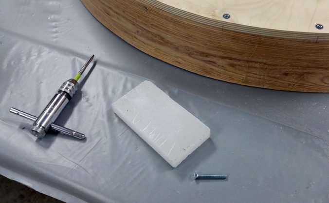
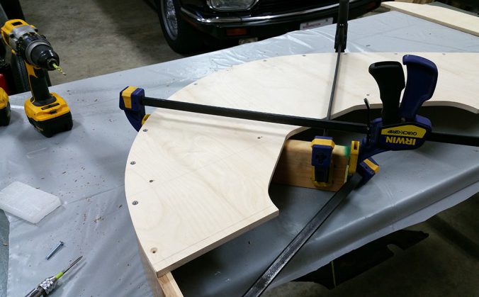
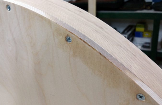
To mechanically attach the arch to the inner panel, I’ll drill through the hole in the plywood with the 9/64″ bit to a depth allowing the use of the 1-1/2″ machine screws, tap that hole, and then drive the screw, using a bit of paraffin on the threads for good luck. I’ll do this hole-by-hole as the arch is pulled into position. Here, I’ve done the first two holes, which can obviously be done without needing to draw the arch into shape.
One lesson learned from the first set: trust the shape of the arch, not the plywood, and only pull the arch.
If pulling the arch to match the plywood for the hole you’re working on makes it so the next hole along requires pushing the plywood out from under the panel, rather than being requiring no adjustment or another pull, the plywood edge where you’re working is low. Leave it low and ignore the appearance, or fill it later. “Low” means 1/16th of an inch; if it was more than this, I would either re-position the arch or make a new inner panel.
The front and back have roughly the same amount of kick-out, though I allowed more at the back, and when initially fitting the inner panel to the arch tried to get smooth, consistent tapers leading away from the starting point.
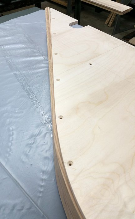
It’s barely visible here, but there is a low spot in the plywood edge between the two holes closest to us. (Because I made the inner panels at the same time, attached to each other, it’s almost certainly on the other panel as well! I’ll be a little concerned if the other arch does not have this defect.) I’ll used some epoxy to fill the low spot, though it doesn’t really matter from a practical standpoint, as nothing on the car will be indexing this inside edge. Still…
In this nicely-blurred photo, you can see that low spot just behind the clamp. You can also see that the rest of the arch will basically need no pressure to match the inner panel, which makes sense as it’s a straight edge. If in doubt, leave a bit of plywood above the arch, though we aim for dead even.
The front corner is problematic, as, in theory, it’s supposed to be vertical here and in the four arches laminated here at Rusty Heaps, it is not.
To get it as close as is practicable, I’m going to pull it back with a moderate amount of force, and since I didn’t have anything to pull against which I felt comfortable about, I’m using this Rube-Goldberg arrangement.
The last screw on the back has to be 1″ in length with corresponding shallow hole, as the arch will only be about 5/8″ wide back here.
Here’s the original left arch, laid upon our now-mechanically-fastened right arch. Matches fairly well. The original was just a wee bit flatter across the top than the arch produced by the form, but barely so.
Ah, math. The new arch needs to be the same dimensions overall as the old arch. Here I’ve done the figures. All that’s missing is a smiley face or, more likely, “see me after class”. For “on this car is ridiculous”, read “with my all-thumbs approach to woodworking, 1/32nd is a joke!”
A line at that distance has been marked on the side of the arch I will be looking at while making the cut.
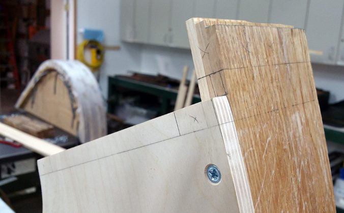
Marking out the cuts I’ll make on the arch before attaching it with epoxy to the inner panel. Some of these lines are just for reference, others I will be cutting now.
The front gets a “notch”, as the outer edge goes to the bottom of the sill board. The notch starts roughly 2″ from the outside edge. The corresponding line parallel to the inner panel is pretty much invisible in this shot.
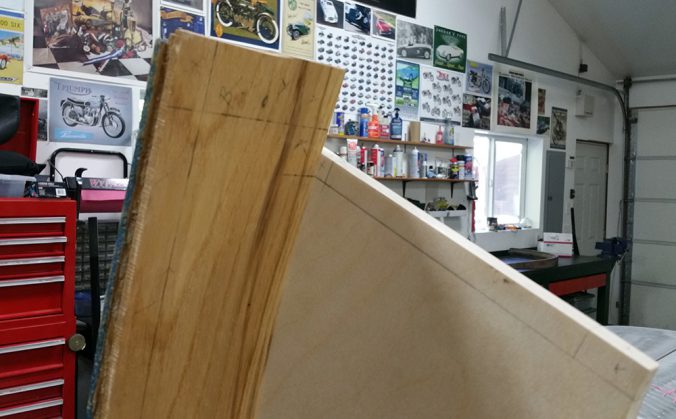
You can see the out-of-vertical nature of the front here. It’s not a big deal, I don’t think. I will cut the rabbet to be true to the sill and there is still a fair amount of “meat” left to the board. (Recall the inner panel is a half-inch long, so my “bottom of the 1-inch-thick sill” line is a half-inch from the bottom of the panel.)
The back gets a simple vertical cut. but I’ve marked a few other points for reference. The dashed line is the back of the chassis on the original. I’ll be cutting the extra half-inch on the bottom of the inner panel to be back from the edge, front and back.
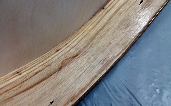
The “final straw” on the first set of these I made was starting the taper too far forward on the board. It starts roughly in the center of where the upper rail attaches to the arch.
I’ve added some arrows in Photoshop to point out my marked cut line. On my car, this taper was not a straight line, it changes to a more dramatic inward slant where the lower rail is let into the arch.
I’ve made the cuts. I’ll do the truing of the front and corresponding rabbet later. Having the inner panel attached will make getting a “true vertical” easier with that much extra area against the saw table.
Here’s my kit for gluing the arch to the panel. Some epoxy, some of the 17-cubic-feet of sawdust so-far produced to mix in for filling the low edge, glue palette, etc., etc. This epoxy has a working time of about 20-30 minutes and sets for sanding in less than 24 hours.
Once again, no photos of the glue-up, too busy for that. I’ve made the bloody thing upside-down, though.
Here is my amateur fill-job on the low spot. I used squeeze-out from the main joint, mixed with sawdust to give it some body. That worked OK, but, as you can see, there were a couple of air pockets. Not a big deal, again, this is just aesthetics on this edge.
I will probably wood-fill or epoxy fill the screw-heads as well before painting the frame, because why not? They’re never coming out again, being glued in place.
On this frame, I am NOT using original fasteners (well, duh). If I could get star-drive or another modern head I would use them in a second. Slotted fasteners look nice but, ye gods do I hate them. Any that might be “publicly” visible will get proper vintage-appearing hardware, but this internal stuff? Give me something you can drive. I don’t much care for cross-head (Philips) either, but that’s what the local hardware joint has.
Here’s the front notch.
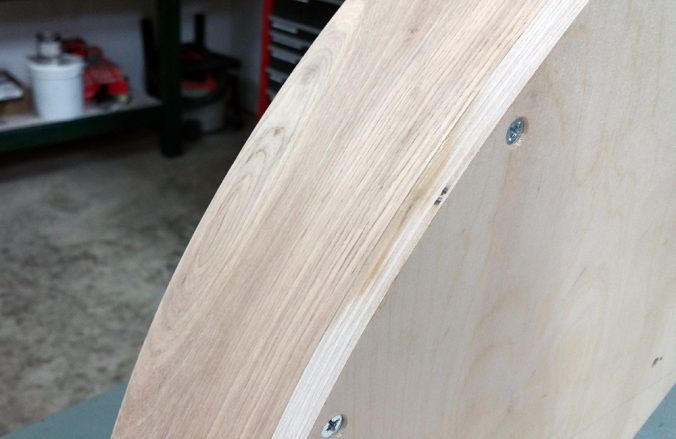
I smoothed and trued-up the entire outside on the drum sander. The idea is to take off the minimum amount needed to show sanding scuffs along the entire width of the ash.
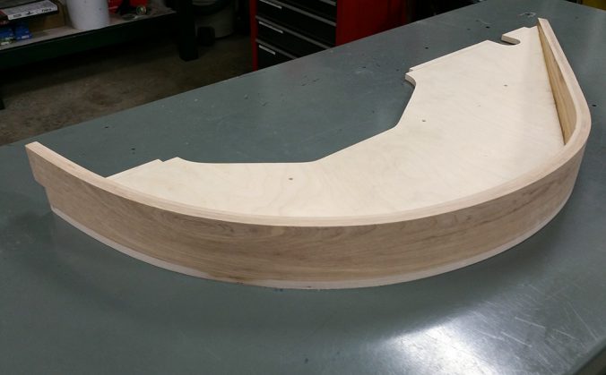
This arch was much truer than my previous efforts, and the goal was to make the ash true and bugger-all the plywood if it didn’t true at the same time. As it was, I only had this one low spot on the plywood edge, and it’s barely low, you can see the sander caught the outside edge of the ply. So, good enough.
Now for the next one, which in some ways is the harder one to build, as ideally it should be a “perfect” mirror of this one. That means a lot of care when placing the arch onto the inner panel to get the curves the same. Fingers crossed!













Duncan
Wow after looking at what you’ve done to accomplish at proper wheel arch I’d let you do some for me any time… when if I need some. Great photos, wonderful lesson.
Beautiful craftsmanship!
I think you just { by accident} built a Broadwood piano { circa 1859-1865} well done!! cheers, J.