
When I first moved into Rusty Keep the plan was to put a two-post lift into the shop. Finally, 12 years later, I spotted a used one I could afford on craigslist which just so happened to coincide with the sale of the Suzuki–so I even had cash to complete the sale. This is the story of installing this beast, no easy task since everything is heavy and needs to go far up into the air.
The guy selling the lift had five of them, which is the only reason I had a chance at this one…normally by the time I respond to CL lift ads they’re gone, if they’re at a reasonable price, and these were very reasonable (he had just replaced all of the lifts in his repair shop with new). In any case, the lift was a couple hours south of me, and my friend Brent agreed to tag along and help me pick it up.
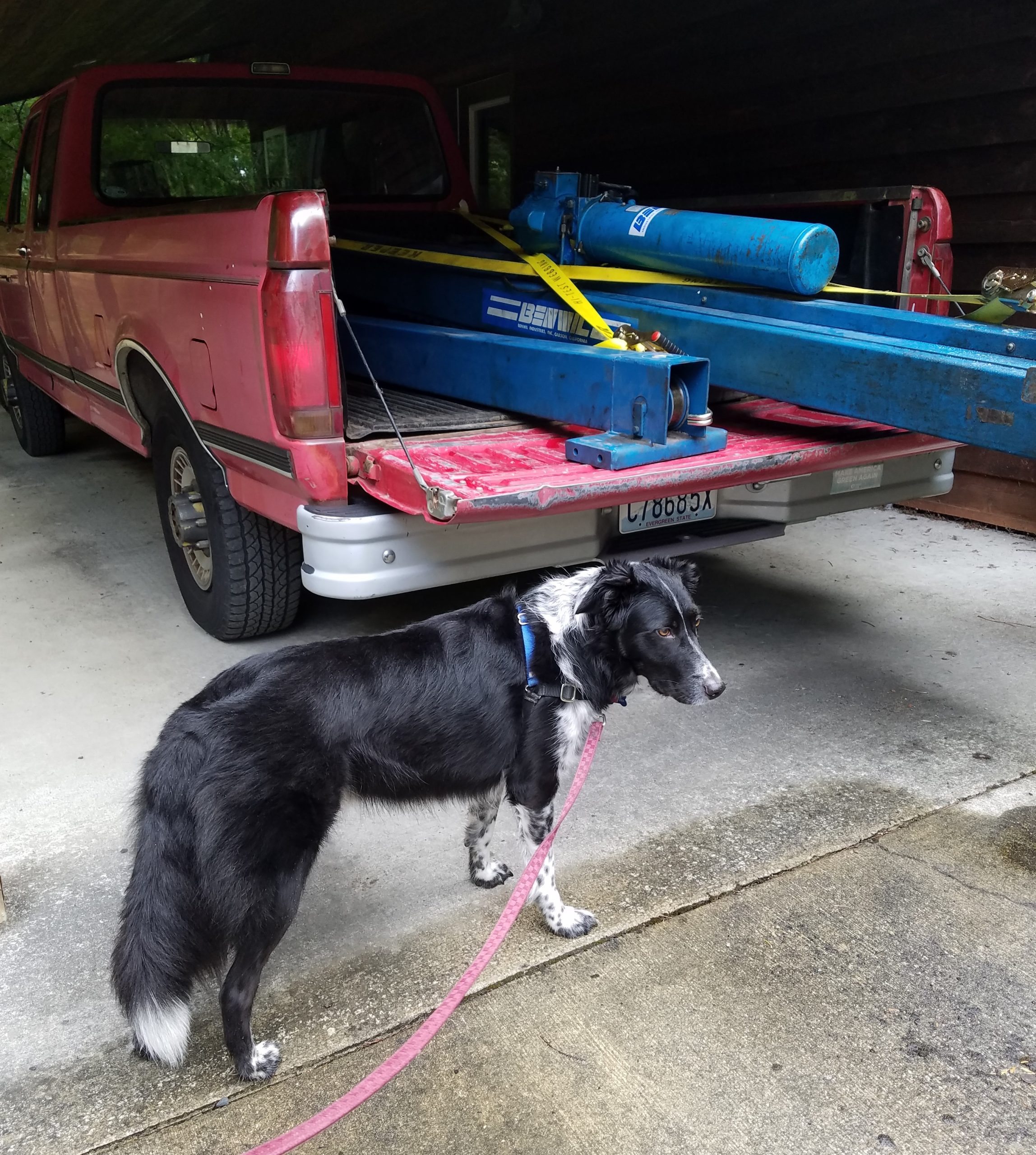
The lift is a Benwil GPO-7, a single-cylinder chain lift with a 7000 pound capacity. Benwil made solid lifts, and installed a ton of them in dealer service bays around the country in the 1980s and 90s…but went out of business in the mid-90s, I gather. This one seems to date from ’91. It’s in fairly decent order, if grubby.
It was a procedure, to say the least, getting this beast loaded into ye olde F250. If the shop owner had not had a small forklift, it would have been impossible. It certainly maxed out the truck’s payload, this thing has got to weigh well over 1500 pounds. In the end, hours later than expected, I ended up back home with a big pile of metal.
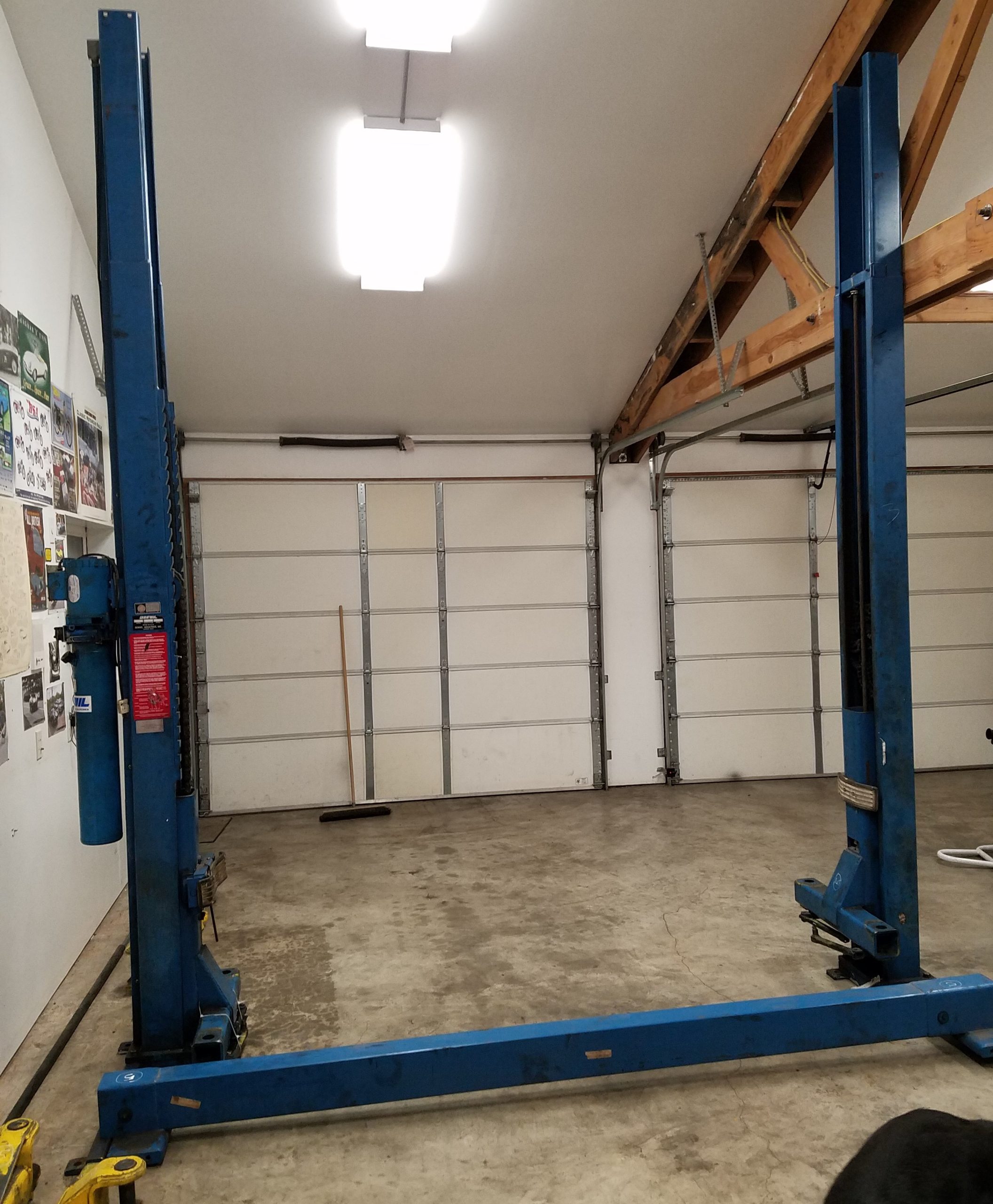
My buddy was kind enough to come up to the island a couple days later and help me unload, which was a sketchy exercise involving engine cranes and luck and whatever brute strength some aging dudes could muster. But we got the bits out and even arranged the posts in approximately the right places, as seen above.
The two big issues still needing attention were:
- Was the concrete slab thick enough? I don’t have an install manual for this lift, but general guidance is at least 4″ of 2500psi concrete under a lift post
- How in the hell is that 250lb cross-beam going to get 12 feet up in the air?
If there was not enough concrete, I would have to remove the existing concrete to 2′ beyond where the posts sit and have a new reinforced pad poured. Expensive, probably more than I paid for the lift. Thankfully, it turns out my slab was over 4″ thick and held the anchor bolts at their full torque, so yay!

I owned a hammer drill, in theory, but it was battery powered, and the first hole took half an hour and three battery packs. So I bought the wired Milwaukee rotary hammer you see in the photo above, which, combined with the fancy carbide four-cutter bit, made pretty short work of the holes. The fasteners are 3/4″ expansion bolts which are torqued to 150lb/ft, a lot for an a guy with a gimpy shoulder. (Don’t tell anyone I carefully used a cheater bar.)
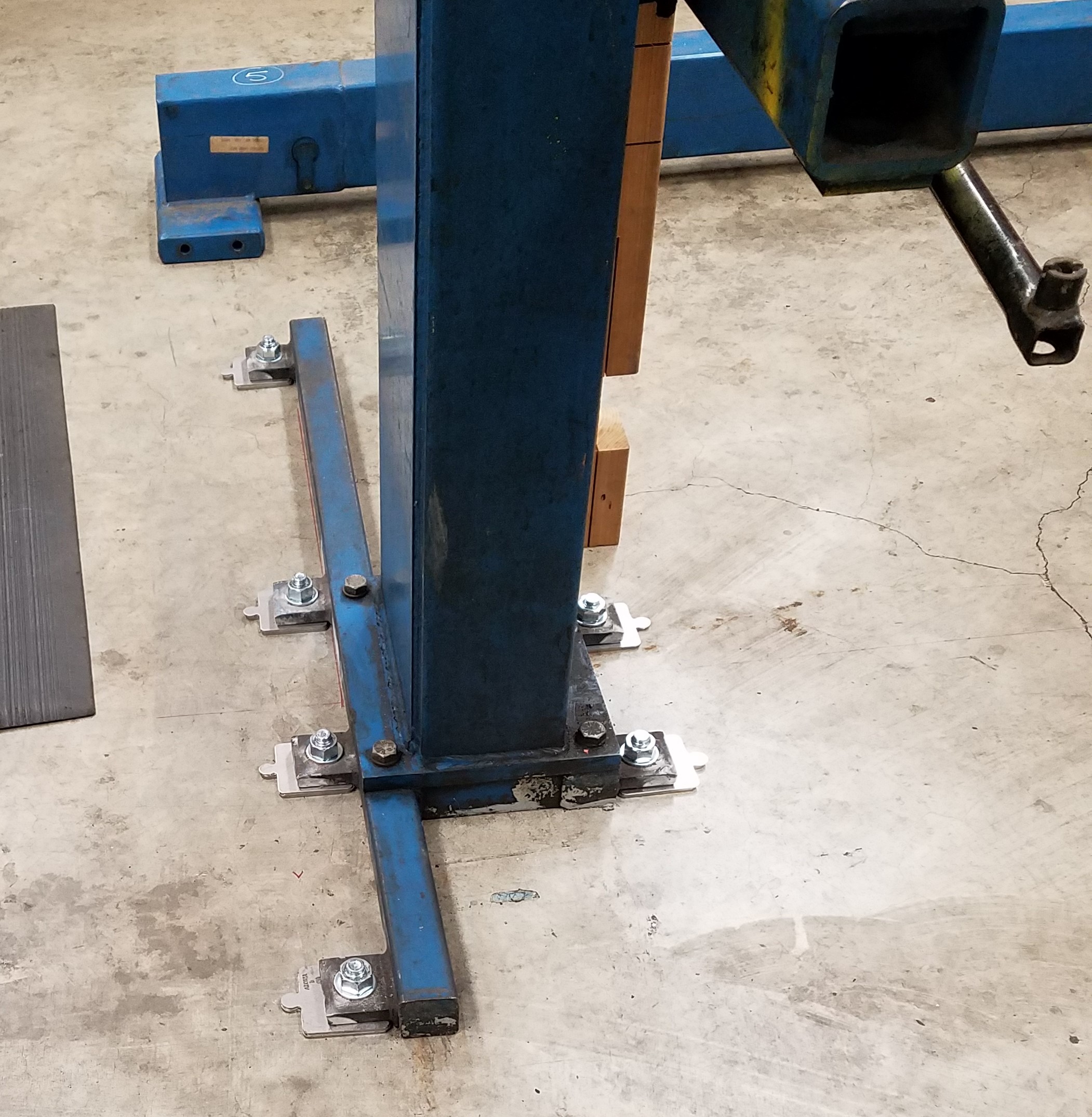
That first post felt like progress but there was a lot left to do. It even turned out plumb, which is what you’d want, of course.
Next the beam had to be lifted up to sit atop the posts before the other post could be bolted in (I think new lifts come with dimensions allowing the posts to be secured before the beam is placed).
I contemplated how this could be done (to be clear, no one was shimmying up ladders and brute-forcing this into place!).
Plan one was to screw a plank across several of the roof joists (this pole building does not have rafters running peak to long outside wall, instead it has joists running parallel to the roof peak, 12′ long 2x6s), with an eye-bolt in it to support a chain hoist. I was never wild about this idea but it probably would have worked.
Plan two was to rent some sort of scissor lift. But I live in the sticks and it would have cost a lot and I’m not sure how it would have got here, especially given my driveway. Never investigated this one.
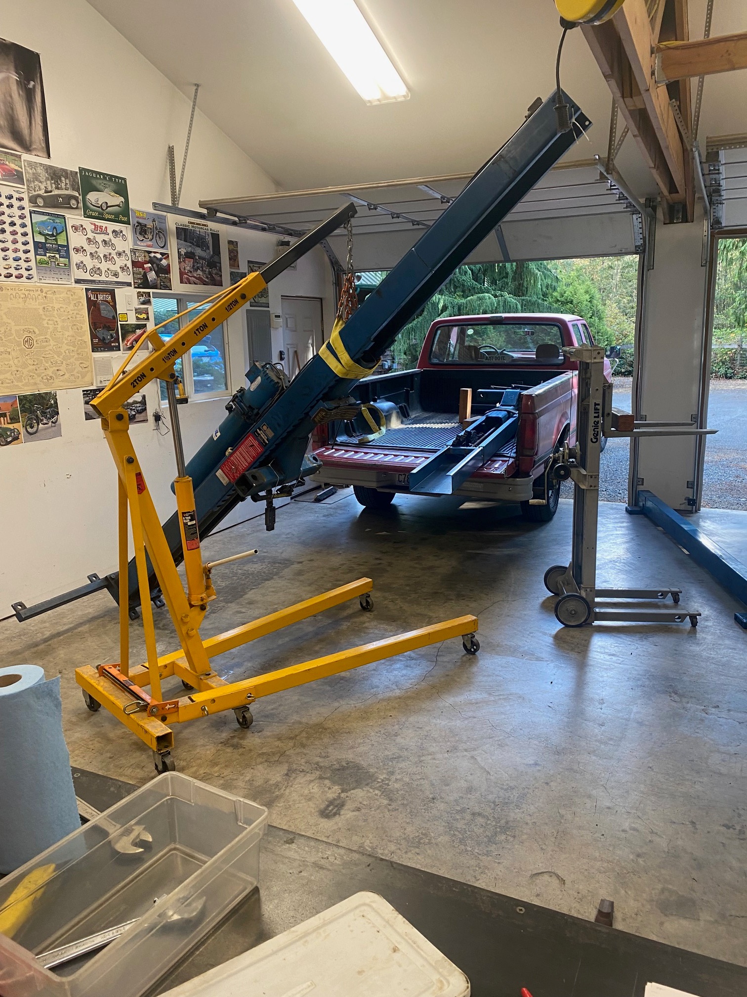
Plan three: I have a Genie lift, a sort of mini-forklift, wound by hand and with a max reach of 8 feet. If I could get it just over 4 feet off the slab, that would give us the needed vertical lift in a very controllable package. (The Genie has a load capacity of 400 lbs, so lifting the beam was well within it’s limits.)
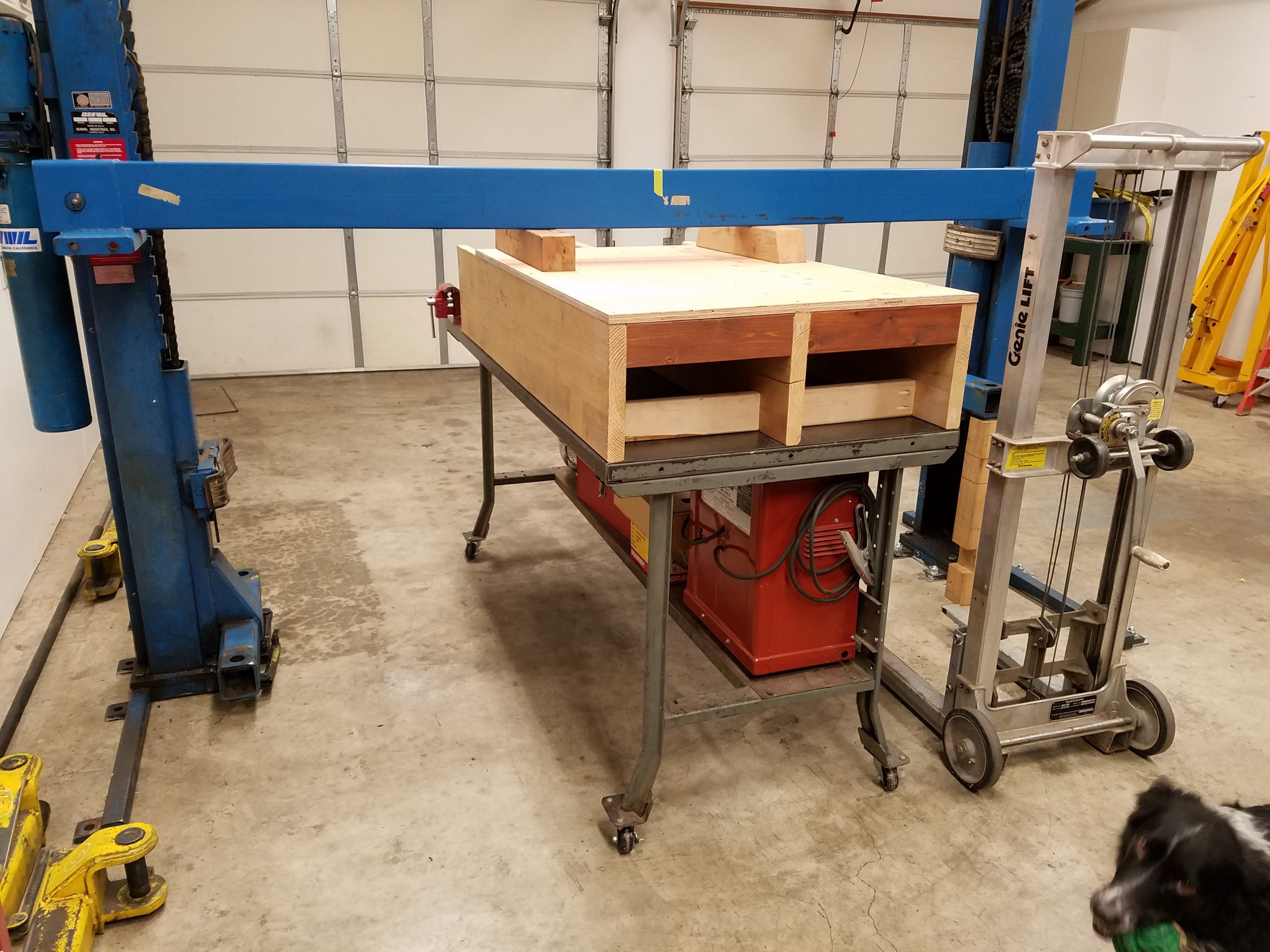
I have a metal workbench on castors which I use as a welding table/portable workbench, and on top of that I built a platform from some old 2x12s on hand and a 3/4″ plywood top (I haven’t bought plywood in ages…jeebus!). I screwed the platform to the table, as seen above. The castors on the table meant we could strap the Genie solidly to the top of the platform and just move the entire contraption to position the beam. I lifted the beam from floor to table using the Genie, and the Genie would be lifted onto the platform once help arrived.
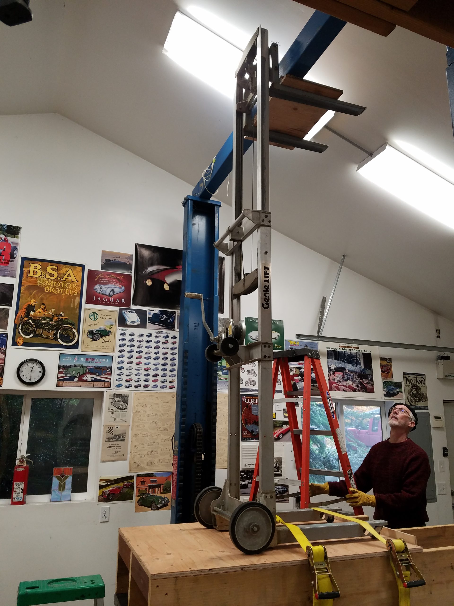
Above you can see the process almost complete. We were bright enough to run some rope through the beam to facilitate pulling the chain across from one side to the other. We also ran a 10′ 2×4 up first to make sure we had enough reach…and the 2×4 was marked with the bolt spacing on the beam, allowing some last minute adjustments of the non-secured post. Matt was kind enough to do most of the ladder scrambling, as I hate climbing ladders. He’s also 4″ taller than my 6’1, which helps.

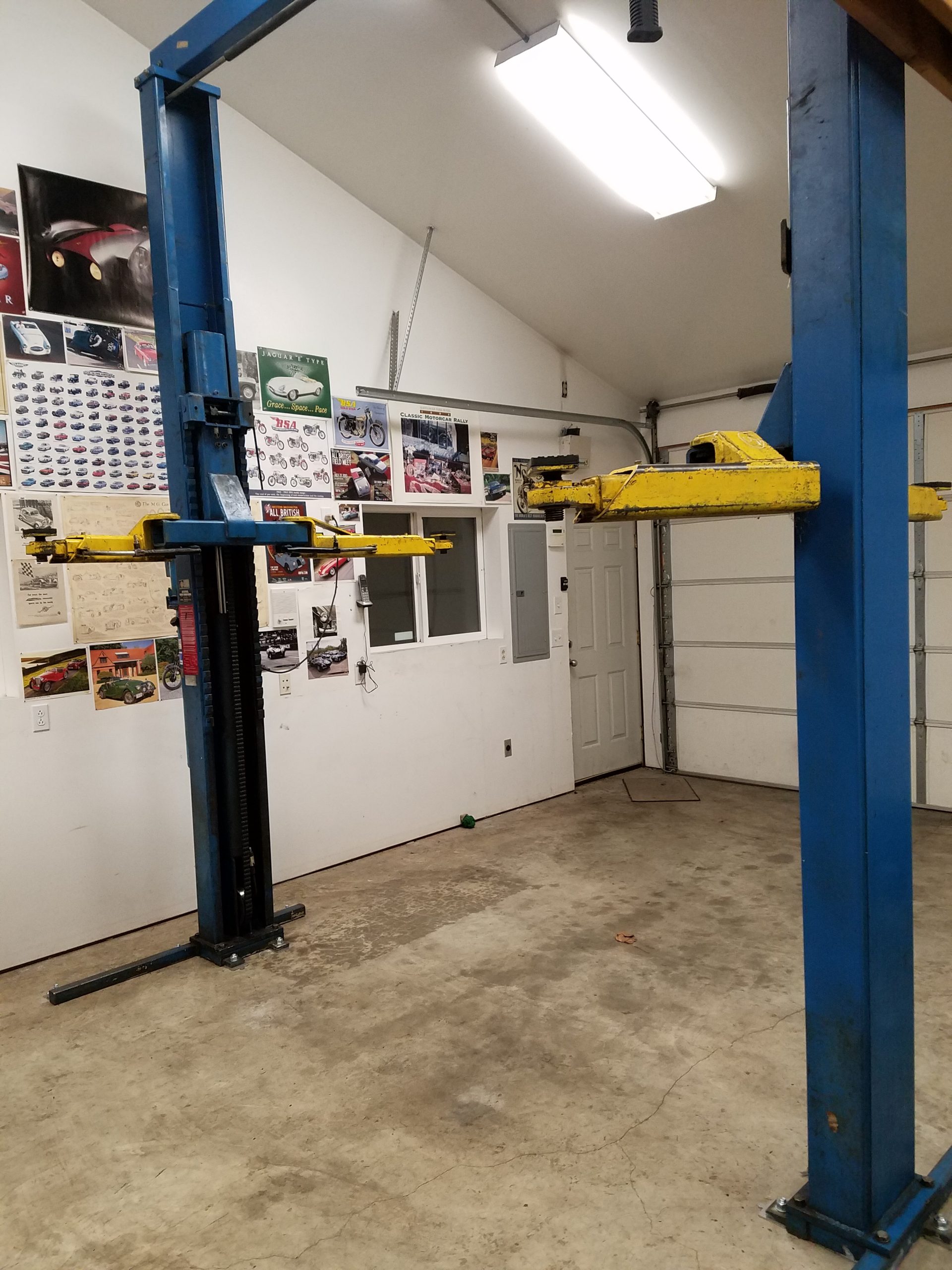
After the beam was placed, we bolted down the remaining post, plumb and parallel with the other. I then put the lift arms onto the carriage and went to test the lift. My special outlet, high on the wall, had no power, despite breaker being on. Hm. Turns out I had wired the wrong wire to that breaker many years ago (breaker has been off all this time, I have no idea what that wire actually goes to) and using my multimeter was able to find the outlet’s wire coiled up in the panel. A few minutes later we had a working lift!
There were a couple of minor mechanical things to attend to. The safety catch on the power pole was not auto engaging; this turned out to be a sheared-off bolt which holds the springs to the axle for that assembly. It was easy enough to fix. The other was some interference on one of the lift arms which prevented it from swiveling more than 15 degrees. A bit of attention with a file saw that put right.
I also scrubbed down the whole thing after it was ready. It’s not perfect, but if you compare the above with the below, hopefully you can see the difference.

I’ll stop rambling here, but I’m happy this install is behind me. Hopefully this will prove to be a useful and reliable asset here in rustyland. I’ll close out with a few more shots of the Morgan on the lift.


Anyway, thanks for reading, hopefully will be back with some rustier content sometime soon.
Bravo!